In the past two decades additive manufacturing (AM) has rapidly evolved from a cutting-edge technology into a routine manufacturing method. The ability to quickly print complex shapes in a cost-effective and energy efficient manner has helped revolutionize the go to manufacturing method in a huge number of industries. Even with this rapid adoption various engineering challenges still exist. One of the most well-known challenges associated with metal additive manufacturing is that pertaining to the varying levels of porosity associated with the 3D printed metal part.
Porosity, what causes it and how can it be minimized?
Porosity occurs when the 3D printed metal part contains hollows or cavities. This incomplete melt is a result of gas pockets forming within the metal powder and variations in the powder granule size. Porosity causes the density of the printed part to be less than the theoretical density of the material. Subsequently, by deviating from the theoretical density of the material, the other properties of the material may deviate from their theoretical values as well. The ultimate result of this is a variety of stresses can develop within the printed part. These stresses can induce various failure mechanisms of the part once it is subjected to its final application including cracking, warpage, metal ball formation, and delamination.
To appreciate the influence of porosity in a printed metal part it can be helpful to look at a simplified example. A perfectly packed cubic centimeter of aluminum would weigh 2.70 g in accordance to the theoretical density of this material (2.70 g/cm3). If one were to weigh a small 3D printed cubic centimeter of aluminum, they can expect the weight of the part to be slightly less than 2.70 g owing to the inevitable porosity existing within the 3D printed material. The extent of the porosity within the material is an imperative metric for the subsequent performance of the part. Within the additive manufacturing industry it is generally desired for the printed material to have less than a few percent porosity, most ideally less than one percent. So, in this example, a 3D printed cubic centimeter of aluminum preferably would not have a weight of any less than ~2.67 g. Even what may seem like a trivial amount of porosity (a few percent) can lead to stress induced failures of the 3D printed part once the part is subjected to its final application and environmental conditions. Monitoring porosity is critical in metal additive manufacturing, as printed parts with the same size and shape may look almost identical externally. These concepts are illustrated in Figure 1.
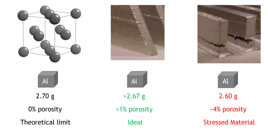
Figure 1: Simplified example of porosity: a hypothetical perfectly packed cubic centimeter of aluminum (left), a more realistic but sufficient material (center), and high stress/porous material (right)1, 2 Adapted
It turns out that porosity often stems back to the properties of the raw material (metal powder) used to conduct the print. Three of the most critical properties of metal additive manufacturing powder are its size distribution, morphology, and chemistry. Figure 2 details these properties and elaborates on how they are important with respect to printing a metal part low in porosity.
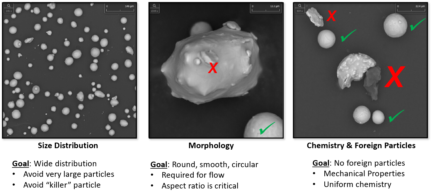
Figure 2: Important characteristics of metal raw material powder for additive manufacturing[3]
Monitoring these powder characteristics can be a daunting task for several reasons. First off, a sufficiently large quantity of powder should be analyzed to ensure an appropriate size distribution is present across a statistically significant portion of powder. Further, within that large quantity of powder, no ‘killer particles’ are present. In this sense, it may be necessary to be able to find the ‘needle in the haystack’ when it comes to analyzing metal additive manufacturing powder: a single particle larger than the print layer thickness can have serious consequences. Secondly, much of this powder exists at a size scale beyond the optical limit; so in order to investigate the various critical elements of the powder’s morphology (i.e. aspect ratio, satellite particles, agglomerates, sphericity, circularity, equivalent circle diameter, elongation, roundness, form factor, etc.) at these small size scales a high powered microscope is required. Finally, the specific chemistry of each individual particle within the powder would ideally be known, as even very small traces of contaminant powder in the powder bed can lead to a drastic change in the properties of the printed part. The culmination of these requirements suggests that to appropriately monitor and characterize metal additive manufacturing powder a high-powered microscope with automation and the ability to simultaneously identify elemental composition would be desired.
The Phenom XL desktop scanning electron microscope (SEM) with ParticleX provides the all in one solution to analyzing the metal powders used in additive manufacturing. In an automated fashion this platform can analyze powders in terms of their size distribution, morphology, and chemical makeup. The system features a large (4” x 4”) sample holder capable of loading up to 30 additive stubs at once. After the powder has been mounted onto the SEM stub the contents of the entire stub can be analyzed and the resultant powder characteristics are reported. Following the analysis, a sortable data table corresponding to the operator’s region of choice is provided along with an EDS spectrum for each particle analyzed during the analysis. A typical set of data output from the ParticleX software is shown in Figure 3.
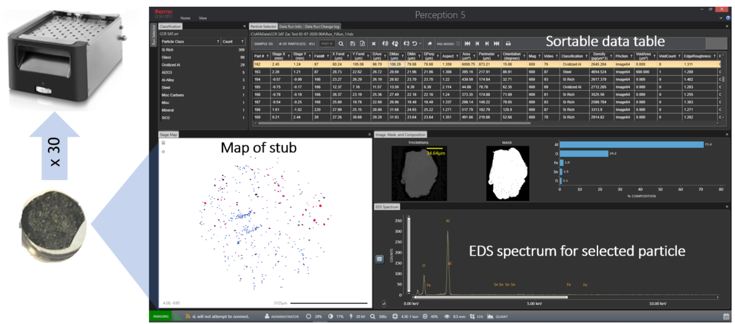
Figure 3: Data output from a ParticleX analysis on additive metal powder raw material[3]
Following the ParticleX analysis reports can be generated based on the parameters of interest. For example, users can plot a histogram distribution of particle sizes which includes the composition of materials within each size bin. An example of this type of output is shown in Figure 4. In this manner, operators can simultaneously (1) determine the size distribution of their powder and (2) identify the elemental composition within each size bin. Such trends may help better understand the importance of contaminant powder in terms of its origin and the influence it will have on the print. Also, by comparing the x-axis (particle size) of Figure 4 to the layer thickness within the print recipe users can select the appropriate print parameters. For example, in Figure 4 it is evident that there are no particles larger than 150 m, suggesting a print layer thickness of 150 m would be safe. However, a few particles are detected in the 100-150 m size range, suggesting there could be porosity issues if a smaller print layer thickness is used with this batch of particles.
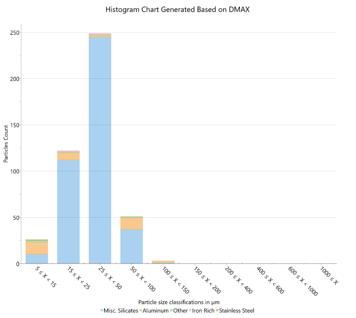
Figure 4: Compositional histogram of additive metal powder particle sizes generated from an automated ParticleX run[3]
Such large particles (agglomerates) often result from powder recycling. It is common for metal AM powders to be recycled due to the high costs of the metal powder. However, great care must be taken when recycling metal powders as their key properties (size distribution, morphology, chemistry) will change as a function of the number of times the powder has been recycled. During the printing process metal particles may get sintered together leading to agglomerates which will negatively influence the powder’s morphological properties during the subsequent print. This leads to one of the most critical questions in metal additive manufacturing:
How many times can my powder be recycled before I need to use fresh powder?
It is well accepted throughout the metal additive manufacturing industry that there is no set answer to this question. The number of times a powder can be confidently recycled is a complex function of many variables: print tool, powder material, powder vendor, print recipe, size of part, etc. On this end, when any of these variables change the ParticleX software can help the researcher reliably answer this question such that best powder recycling practices can rapidly be developed. The ParticleX software can be used to analyze both the incoming virgin powder as received from the vendor as a quality assurance check and also to analyze the recycled powder to investigate how much this powder’s critical properties have deviated from those of the virgin powder. Understanding the influence of changing a variable is only meaningful if consistent work practices are used for preparing and analyzing the powder. On this end, there are various ASTM standards pertaining to the preparation and analysis of the powders used in metal additive manufacturing.
What are some of the ASTM standards used in metal Additive Manufacturing?
A multitude of ASTM standards for preparing and characterizing metal additive powders are used throughout the industry. Nanoscience Instruments works with a variety of samples pertaining to the analysis of additive powders with the Phenom XL desktop SEM and ParticleX. On this end, two of the most relevant ASTM standards4,5 include B215-15 and F1877-16. The first standard discusses collecting an appropriate quantity of material to represent the bulk and the second standard discusses how this material is subsequently characterized. A summary of each of these standards is found below:
ASTM B215-15: Standard Practice for Sampling Metal Powders
This standard covers how a small quantity of metal powder is to be collected such that it is representative of the entire batch of material. The standardized method for obtaining test portions of metal powder are covered considering the possibility of segregation of the metal powder during and after the filling of the containers.
ASTM F1877-16: Standard Practice for Characterization of Particles
This standard covers the proper procedures for characterizing the morphology, quantity, size, and size distribution of particles. The SEM characterization method is included in this standard. The standard defines and depicts critical parameter morphology parameters including equivalent circle diameter (ECD), aspect ratio (AR), elongation (E), Roundness (R), and Form Factor (FF).
In conjunction with the appropriate standards the ParticleX characterization tool can be an invaluable asset to facilitate the optimization of a new additive manufacturing recipe. Figure 5 illustrates that characterization is central to the classic materials science relationship within metal additive manufacturing between processing, structure, properties, and performance. By being able to characterize the raw powder material and understanding its structure it is possible to predict the properties of the predicted part and therefore its anticipated performance.
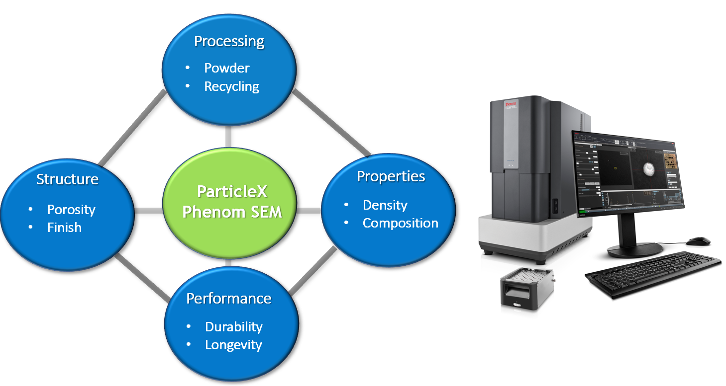
Figure 5: Processing-Structure-Properties-Performance relationship as it pertains to metal additive manufacturing. Characterization is central to understanding the links between these elements.
Additive manufacturing will continue to revolutionize the way the world around us evolves. Taking great care that the printed parts contain minimum amounts of porosity is imperative for the longevity and reliability of the part. By following ASTM standards and utilizing the Phenom XL desktop SEM with ParticleX researchers can investigate the metal powder’s properties prior to the print. This enables optimization of recipes and assists with the recycling of metal powder. As innovations in the field of additive manufacturing continue it will become increasingly important to understand the submicron world such that the macroscopic world around us can continue to become a better place.
- [1] Molitch-Hou, Michael. “VESTA 3 for three-dimensional visualization of crystal, volumetric and morphology data,” J. Appl. Crystallogr., 44, 1272-1276 (2011).
- [3] Gray, Zachary. Characterize materials and products for Additive Manufacturing. Nanoscience Instruments, 01 Apr. 2020.
- [4] ASTM Standard B215-15, 2019, “Standard Practices for Sampling Metal Powders,” ASTM International, West Conshohocken, PA.
- [5] ASTM standard F1877-16, 2019, “Standard Practice for Characterization of Particles,” ASTM International, West Conshohocken, PA.
